Aeronáutica y Aviónica
AMSS applications
AMSS Applications
Season 2004\05
Introduction
All forms of aviation need reliable communications, navigation and surveillance systems to enable them to operate safely and efficiently. The primary means of communications for civil aviation is VHF Radio Telephony (RT) and has been so for over 50 years. During that time the basic features have changed little except for the channel spacing which has gradually been reduced to provide more channels within the available spectrum. The latest reduction to 8.33kHz is probably the last reduction that can be made.
In parallel with the introduction of 8.33kHz channels, the increased use of VHF data links (e.g. Modes 2 and 4) operating in the same band could eventually decrease the amount of voice traffic but only to be replaced with data traffic. In the transition period it is likely that additional channels will be needed to support legacy installations until all aircraft have the appropriate avionics, further increasing the pressure on the VHF band.
Despite the increased number of channels available in the VHF AM(R)S band with 8.33kHz and the increased use of data communications, the growth in traffic is forecast to outstrip the available VHF spectrum by 2015. Therefore new communications systems with scalable growth capabilities (e.g. CDMA type systems) are being considered. Amongst the candidate technologies are satellite systems.
Satellite communications could play an important role in Europe and other parts of the world to provide communications in areas where it is difficult for terrestrial based systems to offer a service. Additionally satellite systems could provide an alternative communications medium to augment terrestrial systems or to act as a back-up system.
Satellite technology is already being used in support of ATS provision. One example of this is the use of satellite communications to support operational ATS in the Norwegian sector of the North Sea. In this area there are many helicopter flights at low level, many of which are beyond coverage of radar or VHF radio communications. Helicopter flights in these areas are required to fit ADS-C equipment and their position is monitored by ATC. This system (known as Modified ADS or MADS) uses the INMARSAT Aero-L system compatible with the ICAO AMSS SARPS to enable the transfer of positional information from the helicopters to the ATC centres. The FANS 1/A system also uses satellite communications to support ATS primarily in remote and oceanic parts of the world.
Objective
This project presents the role of the satellite systems in the current and future time in the Air Traffic Management (ATM). It describes different parts of the Aeronautical Mobile Satellite System (AMSS) and others satellite systems which could be part in the new ATM concept , as well as some developing technology based on such technology.
This document is focused on to give a general idea about the possibilities of the future applications of the AMSS and its importance in the aerospace infrastructure, therefore each element is not deeply described, only to explain his performance and way of working, in addition to its evolution.
The first part consists of an explanation about some concepts about ATM as free flight or gate to gate, which are the goals of the air traffic development, in order to solve the problems in the current airspace exploitation.
The second one (chapters 2, 3 and 4) describes the GNSS concept and all its elements, other satellite systems and some developing technology based in such systems.
The fifth chapter sumarizes the current composition and probable evolution of each scope of CNS with the technology and technics previously mentioned, besides the possibility to develop and implement "gate to gate", "RNAV" and "free flight" concepts.
Last chapter is the conclussion of the project with a speculation about ATM beyond 2020 year and a comparison with the current system.
Concepts
These concepts are part of the navigation strategy for the following years. Their intention is not to define the necessary technology for the air traffic but to fix the goals to be reached in the followings years which allowed to change the present use of the airspace, improving its capacity and safety, and solving the problems that the current infrastructure has.
CNS-ATM
CNS/ATM (Communications, Navigation, Surveillance / Air Traffic Management) describes the technical concepts as well as the implementation of the infrastructure necessary for the provision of air navigation services. This also covers future concepts such as digital Data Links for transmission of operational data, the Automatic Dependent Surveillance (ADS) concept and satellite-based navigation, the Global Navigation Satellite System (GNSS).
ATM is the aggregation of airborne functions and ground-based functions required to ensure the safe and efficient movement of aircraft during all phases of operation. ATM also is used to describe airspace and air traffic management activities that are carried out jointly by aeronautical authorities concerned with the planning and organization for the effective use of airspace and its movements within their regions of responsibility. The ATM operational concept must have a visionary scope and be referred to the concept of endurance of flight, shared separation assurance and situational awareness in the cockpits. The general objective of the ATM is to allow aircraft operators to comply with the estimated times of departure and arrival and to follow preferred flight profiles with a minimum of limitations and without jeopardizing agreed level of safety.
The communication element of CNS/ATM systems provides for the exchange of aeronautical data and messages between aeronautical users and/or automated systems. Communication systems are also used in support of specific navigation and surveillance functions.
The navigation element of CNS/ATM systems is meant to provide accurate, reliable and seamless position determination capability, worldwide, through the introduction of satellite-based aeronautical navigation or global navigation satellite system (GNSS). Nowadays based on ground systems provide this service, as DME, VOR or NDB.
The surveillance element of CNS/ATM provide the required level of safety, keep the distance between aircrafts and other objects (other airplanes, ground vehicles, mountains....) for avoiding accidents. Surveillance systems presently in use can be divided into two main types: dependent surveillance and independent surveillance. In dependent surveillance systems, aircraft position is determined on board and then transmitted to Air Traffic Control (ATC). The current voice position reporting is a dependent surveillance systems in which the position of the aircraft is determined from on-board navigation equipment and then conveyed by the pilot to ATC by radiotelephony. Independent surveillance is a system which measures aircraft position from the ground. Current surveillance is either based on voice position reporting or based on radar (primary surveillance radar (PSR) or secondary surveillance radar (SSR)) which measures range and azimuth of aircraft from the ground station.
RNAV
Random Navigation (RNAV) is a method of navigation which permits aircraft operations on any desired flight path within the coverage of station referenced navigation aids or within the limits of the capability of self-contained aids, or a combination of these. Airborne RNAV equipment automatically determines aircraft position by processing data from one or more sensors and guides the aircraft in accordance with appropriate routing instructions.
Additional navigation parameters such as distance and bearing to a preselected waypoint can also be computed from the aircraft position and the location of the waypoint, dependent upon the capability of the RNAV equipment. Position can be displayed to the pilot in various ways, most practically in terms of the aircraft position relative to the precomputed desired track. Most RNAV equipment can employ any lateral displacement of the aircraft from the desired track to generate track guidance signals to the auto-pilot. With other less sophisticated RNAV equipments manual corrective action is taken by the pilot.
The benefits offered for this concept are:
-
improved management in the flow of traffic by repositioning of intersections;
-
more efficient use of available airspace, by means of a more flexible ATS route structure and the application of the Flexible Use of Airspace (FUA) Concept, permitting more direct routes (dual or parallel) to accommodate a greater flow of en-route traffic;bypass routes for aircraft overflying high-density terminal areas; and alternative or contingency routes on either a planned or an ad hoc basis;
-
reduction in flight distances resulting in fuel savings;
-
reduction in the number of ground navigation facilities.
Required Navigation Performance (RNP) is a statement of the navigation performance accuracy necessary for operation within a defined airspace. The different characteristic of each kind of RNAV are shown in the following table:
| RNP Type | Required Accuracy | Description |
| 0.003/z | ± 0.003 NM [± z ft] | Planned for CAT III Precision Approach and Landing including touchdown, landing roll and take-off roll requirements. (ILS, MLS and GBAS) |
| 0.01/15 | ± 0.01 NM [± 15 ft] | Proposed for CAT II Precision Approach to 100 ft DH (ILS, MLS and GBAS) |
| 0.02/40 | ± 0.02 NM [± 40 ft] | Proposed for CAT I Precision Approach to 200 ft DH (ILS, MLS, GBAS and SBAS) |
| 0.03/50 | ± 0.03 NM [± 50 ft] | Proposed for RNAV/VNAV Approaches using SBAS. |
| 0.3/125 | ± 0.3 NM [± 125 ft] | Proposed for RNAV/VNAV Approaches using Barometric inputs or SBAS. |
| 0.3 | ± 0.3 NM | Supports Initial/Intermediate Approach, 2D RNAV Approach, and Departure. Expected to be the most common application. |
| 0.5 | ± 0.5 NM | Supports Initial/Intermediate Approach and Departure. Only expected to be used where RNP 0.3 cannot be achieved (poor navaid infrastructure) and RNP 1 is unacceptable (obstacle rich environment) |
| 1 | ± 1.0 NM | Supports Arrival, Initial/Intermediate Approach and Departure; also envisaged as supporting the most efficient ATS route operations. Equates to P-RNAV. |
| 4 | ± 4.0 NM | Supports ATS routes and airspace based upon limited distances between navaids. Normally associated with continental airspace but may be used as part of some terminal procedures. |
| 5 | ± 5.0 NM | An interim type implemented in ECAC airspace to permit the continued operation of existing navigation equipment. Equates to B-RNAV. |
| 10 | ± 10 NM | Supports reduced lateral and longitudinal separation minima and enhanced operational efficiency in oceanic and remote areas where the availability of navigation aids is limited. |
| 12.6 | ± 12.6 NM | Supports limited optimised routing in areas with a reduced level of navigation facilities |
| 20 | ± 20.0 NM | The minimum capability considered acceptable to support ATS route operations. |
Accuracy is not the only paremeter which describe each kind of RNP, the rest of them are shown below in the capter concerning GNSS.
Free Flight
The Radio Technical Committee for Aeronautics (RTCA) defines "Free Flight" as: "a safe and efficient flight operating capability under Instrument Flight Rules (IFR) in which operators have the freedom to select this path and speed in real time. Air traffic restrictions are only imposed to ensure separation, to preclude exceeding airport capacity, to prevent an authorized flight through special use airspace, and to ensure safety at flight. Restrictions are limited in extent and duration to correct the identifies problem." In the same report RTCA states that "Free Flight is necessary to reduce the insufficient capacity, limited access and excessive restrictions that have resulted in escalated operation costs, increased delay and decreased efficiency for all users" .
Gate to Gate
Gate to gate is a new way to manage a flight, it consists in the total control of all parameters which involve an aircraft during the route, since it starts the engines till their stopping. In this way it is possible to choose the more reliable configuration to obtain the lowest fuel consumption, the shortest path, the highest level of safety and sumarizing the best advantage of the available resources.
The implementation of all aforementioned concepts is the solution adopted by ICAO (Internation civil Aviation Organization) to solve the current and foreseen problems of the present air traffic system, and they are the goals to reach for the developing techonology.
-
GNSS
The Global Navigation Satellite System (GNSS) is the name given by ICAO to include all elements of satellite navigation and its augmentations, both present and future. The creation of that concept is due to the necessity of change the current system of navigation.
The rate of growth per year of the air traffic in Europe is almost a 5%, and the present distribution of air space has a limit capacity which is supossed to be exceeded over the year 2010. The aircrafts fly following paths predetermined by some based on ground aids, as DME,NDB or VOR, so they cannot choose the shortest way to fly from one place to another having to adapte the routes to the existing aids; therefore there are a kind of "highways" which concentrate all the traffic movements, it means the air space is being bad exploiting,and it supposes big costs of money for the air companies.
Besides this, in some areas like oceanic or remote ones, it is impossible to stablish a net with ground based systems and the safety distance has to be strongly increased. Such reasons made ICAO to consider the possibility to create a global navigation system based on satellite, taking advantage of the existing systems, GPS, GLONASS and INMARSAT.
The study about the implementation and feasibility of such type of navigation system began at the beginning of the 90´s. Nowadays, the purpose is to develope the necessary technology to allow GNSS cover all CNS tasks, not only to provide navigation service but surveillance and comunication also; and perhaps, beyond the 2020 year, to be the sole system for the air navigation, although this question is debatable.
The disadvantages presented by this system are:
-
The vulnerability of the satellite signals to get interferences.
-
The accuracy of the position determination is variable in time and space setting statistical limits on its performance.
-
the institutional issue of GNSS signals being controlled by only a few nations and there is no performance guarantee provided by the current constellation operators.
In the other hand it has the following advantages over conventional ground aids:
-
GNSS receivers work globally, they are not restricted by the range of a ground transmitter.
-
Satellite navigation is more accurate in most respects compared to other methods.
-
GNSS receivers offer flexibility, they do not restrict the user to a fixed route structure.
-
GPS receivers are low cost and readily available; a global mass market of applications has driven down their price.
-
Satellite navigation is less expensive for aviation to use. The U.S. and R.F. taxpayers carry the current costs through their respective defence budgets, whereas conventional air navigation systems recover their costs from the aviation community. Galileo's cost will be, at most, only partially carried by aviation.
-
GNSS is the only technology offering the capability to support gate-to-gate navigation. Currently several different navigation aids must be carried, one or more for each phase of flight and region.
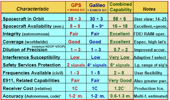
To summarize; GNSS plays an important role in the development of the new ATM, making feasible the implementation of such concepts as free flight, free route, 4DRNav and even "gate to gate". However it couldn´t achieve the features required of continuity, availability, integrity and accuracy for all the phases of flight using only the satellites constellation aforementioned, therefore it is necessary to improve with other technology. Required performances are shown in the following graphic:
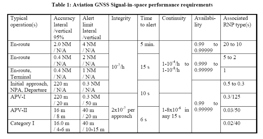
To reach this features GNSS covers a wide variety of systems: GPS, GLONASS, SBAS (EGNOS, WAAS, MSAS), GBAS (LAAS), RAIM, ABAS and in future GALILEO, GPS III, GLONASS-K. Its final composition will depend on the requirements for air navigation. It is assumed that ICAO will continue to write amendments to standardize GNSS up to the point where it could be adopted as a sole-service. Next table shows the differents future components of GNSS and the time of their implementation.
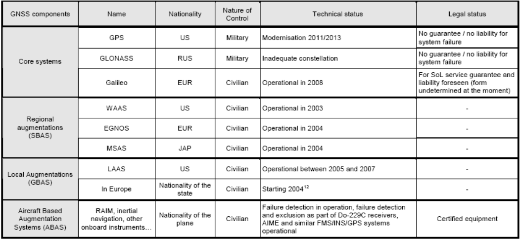
Today's GNSS components are:
-
GPS,
-
GLONASS;partially operational, with doubts on its availability in the future)
-
ABAS; Receiver Autonomous Integrity Monitoring (RAIM) algorithms, Inertial Navigation Service (INS) hybridisation with GPS.
These system reach the lowest features allowed by ICAO for aircraft navigation. It is inadequate for supporting precision approach.
The implementation of GNSS has been divided in parts, nowadays the 2 first parts are defined and known as GNSS-1 and GNSS-2; the configuration of the third part is still under discussion.
GNSS-1 is mainly formed by the two constellations currently working, GPS and GLONASS and by the SBAS systems, as is shown in the graphic below .
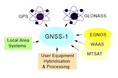
Using SBAS the features of the navigation signal is enhanced and an integrity signal is added. This allows to use that system for almost all phases of flight, however it is still necessary to set local systems for approaching phases of flight.
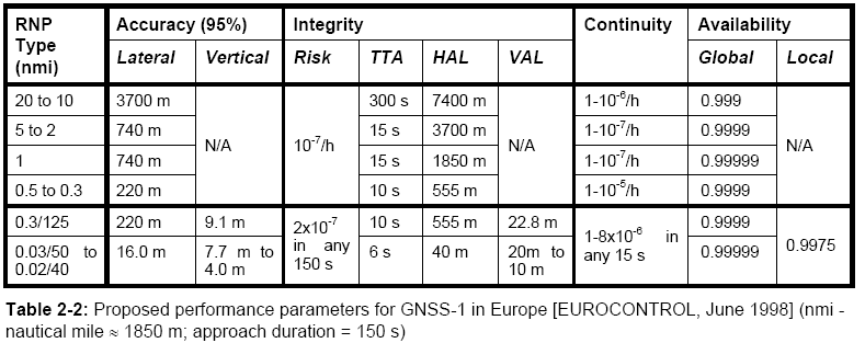
The expected performance for the GNSS-1 in Europe is shown in the following table:
The second generation, GNSS-2, enhance all the previous features incorporating the european global navigation system, GALILEO, and the next generation of GPS. It will offer a service for almost all the phases of flight without any kind of augmentation, except in precission approachings where ground augmentations are necessary to reach the standards of ICAO.
In the following graphic are shown the difference between each navigation system perfomance and when both are used at the same time.
Global position constellation
Global Position System (GPS)
Satellite-based radio navigation system, initially developed in the early 1960s and operated by the U.S. Department of Defense (DOD) since then. However, subsequent to a 1966 Presidential Decision Directive which was later passed into law, the "ownership" from DOD was transferred to an Interagency GPS Executive Board (IGEB), co-chaired by senior officials of the Departments of Transportation and Defense to provide management oversight and to assure that GPS meets both civil and military user requirements.
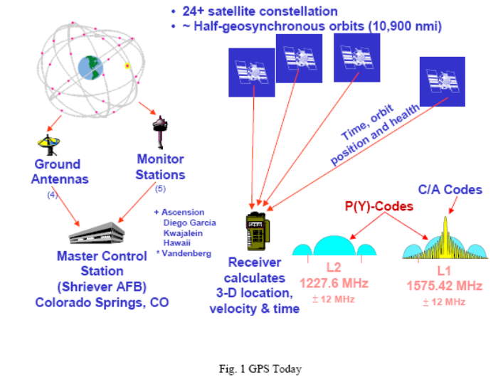
The space segment is composed of 24 satellites (this constellation is called NAVSTAR) with a useful life of approximately 7.5 years, arranged in 6 orbits of four satellites each at an altitude of 20,200Km, such orbits are nearly circular and equally spaced about the equator at a 60-degree separation with an inclination of 55 degrees relative to the equator. users with a clear view of the sky have a minimum of four satellites in view.
At the heart of the Ground Control Network is the Master Control Station (MCS) located at the Schriever (formerly named Falcon) Air Force Base near Colorado Springs, Colorado . The MCS operates the system and provides command and control functions for the satellite constellation.
The satellites in orbit are continuously tracked from six USAF monitor stations spread around the globe in longitude: Ascension Island , Diego Garcia, Kwajalein , Hawaii , Cape Canaveral and Colorado Springs . The monitor stations form the data collection component of the control network. A monitor station continuously makes pseudorange measurements to each satellite in view. There are two cesium clocks referenced to GPS system time in each monitor station. Pseudorange measurements made to each satellite in view by the monitor station receiver are used to update the master control station's precise estimate of each satellite's position in orbit.
GPS provides two levels of service; a Standard Positioning Service (SPS) for general civil use; and a Precise Positioning Service (PPS) primarily intended for use by the Department of Defense and U.S. allies.
There are no restrictions on SPS usage and is available to users worldwide. But these signals are affected to deteriorate his accuracy, it is called Selected Availability (SA). UTC (USNO) time dissemination accuracy is within 340 nanoseconds (95%) referenced to the time kept at the U.S. Naval Observatory. It means that the precision without the SA effects would be large better, in the order of 30 meters. PPS provides UTC (USNO) time transfer accuracy within 200 nanoseconds (95%) referenced to the time kept at the U.S. Naval Observatory.
The accuracies of all differents kinds of service are shown in the following table:
| Accuracy (95%) | SPS(SA) | SPS | PPS |
| Horizontal (m) | 100 | 25 | 22 |
| Vertical (m) | 156 | 43 | 27.7 |
At this time GPS doesn´t offer a signal of integrity and is the main reason why is not used for air navigation.
U. S. Government is preparing the next generation of GPS (GPS III) broadcasting a new frequency and developing a modern satellite. The activities to enhance the GPS performance are:
-
New civil frequencies at L2 (1227.6 MHz) and at L5 (1176.45 MHz), as well as retention of the long-standing civil signal at L1 (1575.42 MHz). It allows to civil users to correct ionospheric deviation.
-
New signal structures for both civil and military users. The new civil signals at L5 are projected to support a code rate 10 times that of the C/A-code. This will improve code measurement accuracy, reduce code noise, reduce cross-correlation concerns, and provide improved multipath mitigation.
-
Removal of Selective Availability, This, with the additional civil frequencies (for ionospheric correction), will improve civil GPS performance by a factor of about ten (compared to that with SA).
-
Reduction in Systematic Error Sources includes not only SA removal and ionospheric error correction, but substantial improvements in GPS receivers, in the control segment redundancy (with the added NIMA monitor stations), and improved statistical estimation techniques providing substantially better capabilities for minimizing spacecraft position prediction (ephemeris) errors.
-
Increased Signal Availability and Power from GPS Spacecraft which have greater reliability and lifetimes.
-
GLONASS
-
Galileo
-
SBAS
-
WAAS
-
EGNOS
-
MTSAS
-
GBAS
-
DGPS
-
LAAS
-
RTK
-
GRAS
-
VDL
-
VDL Mode 1
-
VDL Mode -2
-
VDL Mode 3
-
VDL Mode 4
-
ABAS
-
RAIM
-
• Navigation solution with RAIM;
-
• 2D or 3D navigation solution without RAIM; and
-
• Dead Reckoning (DR), or loss of navigation solution.
-
RAIM (FD)
-
RAIM (FDE)
-
AAIM
-
Communication Systems
-
INMARSAT
-
Swift64; based on Inmarsat's Global Area Network (GAN) technology, Swift64 offers Mobile ISDN and IP-based Mobile Packet Data Service (MPDS) connectivity at a basic rate of 64kbit/s to support high-quality voice, fax and data communications. Techniques such as channel bonding and data acceleration can boost the effective data rate to beyond 0.5Mbit/sec.
-
Aero H; the original Inmarsat voice and data service, it supports multichannel voice, fax, data communications at up to 9.6kbit/s, it complys with the ICAO requirementes about safety and air traffic control.Aero H+ is an evolution of Aero H. When an Aero H+ equipped aircraft is operating within a high-power spotbeam from an Inmarsat I-3 satellite it can receive Aero H levels of service at lower cost. Outside the spotbeams the terminal works with the global beam as if it were a standard Aero H system.
-
Aero I; exploiting the spotbeam power of the Inmarsat I-3 satellites. Aero I brings multi-channel voice, fax and data at up to 4.8kbit/s through smaller, cheaper terminals.
-
Aero L; low-speed (600 bit/s) real-time data, mainly for airline ATC, operational and administrative communications. It complys with the requirements of ICAO about safety and air traffic control, as well as aero-H.
-
mini-M; aero Single-channel voice, fax and 2.4kbit/s data for small corporate aircraft and general aviation.
-
Aero C ; it allows non-safety-related text or data messages to be sent and received by general-aviation and military aircraft operating almost anywhere in the world. Aero C operates on a store-and-forward basis - messages are transmitted packet-by-packet, reassembled and delivered in non-real-time. This is the aeronautical version of the other of the services offered by INMARSAT.
-
INTELSAT y EUTELSAT
-
IRIDIUM
-
New technologies and developing projects
-
VSAT
-
Time Division Multiplexing, a satellite channel divided into time slots for transmission from a central hub to a group of VSAT sites. Individual time slots can be addressed specifically to one or more VSATs. Usually used as the access protocol for the outbound channel (hub to VSAT) of a VSAT system.
-
Time Division Multiple Access, a contentious access satellite channel which is divided into time slots for sharing between VSATs at different sites usually for connection to a hub. Usually used as the access protocol for the inbound channel (VSAT to hub) of a VSAT system.
-
SDLS
-
Aircraft positioning data that complements that from traditional infrastructures (radar, etc.), to be used by air traffic control.
-
Technical data to increase aircraft operating efficiency.
-
Use of Geostationary Satellite transparent transponders, with mobile access in AMS(R)S band (aeronautical sub-band),
-
CDMA access technique,
-
Decentralised access capability,
-
Incremental deployment.
-
MASSAO y Aerofleet projects
-
Cockpit display CDTI-2000. This display is the user terminal of the air fleet management system to the air crew and will allow the review and the creation of messages over the satellite communication link. It is further capable of presenting data sent from ground to the crew in graphical way (e.g. weather information, mission dependent area of operation). This display will interface with the airborne part of the Satcom equipment to provide further communication functions without flight crew involvement. The CDTI-2000 is certified to be used in aircraft.
-
Iridium satellite transceiver. A certified transceiver will provide a global, constant, and reliable link between the aircraft or the helicopter and the dispatch center of the operator on the ground.
-
Dispatch station software. This software allows the dispatch personnel on the ground to communicate with the flight crews and to visualize information sent from the aircraft (e.g. position reports, status messages, etc).
-
OPTIMAL project
-
To define new/enhanced operational procedures for approach and landing, for aeroplanes and rotorcrafts also, in order to increase capacity, efficiency and safety, and decrease noise exposure, using advanced navigation functions and enhanced ATM.
-
To assess in full scale / real life the near-term approach & landing procedures and the associated airborne and ground functions.
-
To study and experiment more longer term (beyond 2015) functions (airborne and on ground).
-
To close the gap between capacity in low visibility conditions and good visibility conditions.
-
To increase the arrival rate at major airports significantly above the level achieved by current best practices.
-
To better accommodate commuter and general aviation aircraft.
-
To allow aircraft / rotorcraft simultaneous IFR operation, in order to generate additional capacity.
-
To reduce the environmental impact by avoiding urban areas and by optimising the noise & gas emission during landing phases (i.e. continuous descent profiles).
-
To accelerate the introduction of Approach Procedures with Vertical Guidance (APV).
-
To take full advantage of the RNP-RNAV capabilities that are now available.
-
To increase Safety using vertical guidance.
-
Conclussions
-
Role in CNS/ATM
-
Gate to gate?
-
Technology; a seamless system of navigation, a reliable way of communication for data and voice, a surveillance system with a high level of safety for all phases of flight, a software which supports pilots and airtraffic controllers tasks, are some examples of the neccessities which have to be solved by the new technology.
-
Definition; it means to coordinate all technology and human resources to define clearly the gate to gate concept; how it exacly will work, what need each user of the ATM, which will be the new tasks for the crew and the air traffic controllers.
-
Implementation; to apply the concept and make it works, it is the last step but the most difficult of them because has to consider the pecualirity of every place and adapt to the situation.
-
New system beyond 2020
-
Services to passengers as internet access, fax and telephony. Due to the importance of communication in current bussiness and the high improvement of such sector, it is foreseen a great quality of that kind of services with a low cost for users.
-
Broadcast of weather and other traffic information. Not only INMARSAT and GNSS can provide this service. IRIDIUM constellation with a global coverage and other private companies will be able to offer this service with guarantee and assure a best reliability of information.
-
To enhance the navigation performance delivering the GPS or GALILEO signal in order to increase the coverage, accuracy and integrity.
-
Using the VSAT technology ans satellites from private companies, for instance IRIDIUM, INTELSAT or EUTELSAT, create a net for data link between all the air traffic control stations, air companies and aircrafts to allow a gate to gate management in real time and even to participate in surveillance tasks.
-
Comparison with the current ATM system
-
Acronyms
-
Bibliography
-
webpages
-
http://www.iss-eu.org
-
http://europa.eu.int
-
http://esamultimedia.esa.int
-
http://www.gisdevelopment.net
-
http://gps.faa.gov
-
http://www.redsword.com
-
http://www.glonass-center.ru
-
http://www.upv.es
-
http://inmarsat.com
-
http://www.intelsat.com
-
http://www.eutelsat.com
-
http://www.thales-navigation.com
-
http://esamultimedia.esa.int
-
http://www.esa.int
-
http://www.oosa.unvienna.org
-
http://www.icao.int
-
http://www.mlit.go.jp
-
http://www.aticourses.com
-
http://telecom.esa.int
-
http://www.webopedia.com
-
http://www.comsys.co.uk
-
http://www.satsig.net
-
http://www.alcaltel.com
-
http://telecom.esa.int
-
http://www.eurotelematik.de
-
http://www.optimal.isdefe.es
-
http://www.ato.gov.ph
-
documents (all of them are in internet)
-
Appendix
-
Techniques of modulation
-
Standards and recommended practices in annexes 1,6 and 11
-
1. They are limited to radiotelephony communication: The scope of the new Standards are limited to radio communication and they do not address issues related to language used in the cockpit or communication on the ground between flight crew and ground personnel.
-
2. They cover all languages used in radio communication: The Standards cover all languages used in radio communication and not only English. The reason is that any person should be reasonably fluent in a language if she/he chooses or is required to use that language for radio communication. Nevertheless, it remains a fact that most of the implementation challenges are related to English proficiency as (1) English is the only language available on a worldwide basis and (2) when another language is used, it is generally done between persons who are at the expert level.
-
3. The “speak and understand” Standard: Because the Standard is limited to radiotelephony communications, it only involves oral communication and can be described as a “speak and understand” Standard. It does not include reading and writing abilities. This has some important consequence when it comes to testing because most of the commercially available tests focus on reading and writing abilities and they are not appropriate in this context. This is a point that will be covered in some detail during the Symposium.
-
4. Assessment using a rating scale (Level 4): A significant aspect of the Standards is that the proficiency level is defined in a precise and scientific way by a rating scale and holistic descriptors.
-
5. Progressive implementation: The Air Navigation Commission and the ICAO Council recognized that the implementation of the new language proficiency Standards and in particular the rating scale would be challenging. It therefore agreed on a progressive implementation of the language Standards as it is outlined in the chart. Generally speaking, the basic “speak and understand” Standard became applicable on 5 march 2004 and the rating scale will have to be used to assess the “speak and understand” Standard as of 5 March 2008. There are some small variations depending on the licence, which are addressed in this presentation.
-
1. They shall demonstrate the ability to speak and understand the language used for radiotelephony communications (Standard 1.2.9.1); and
-
2. After 5 March 2008, the ability to speak and understand the language used for radiotelephony communications shall be demonstrated to Level 4 of the ICAO rating scale (Standard 1.2.9.4 and Appendix). In addition, recurrent testing will be required for those below Level 6.
-
1. All Air Traffic Controllers and Aeronautical Station Operators, i.e. existing and new licence holders have to meet the “speak and understand” Standard.
-
2. All holders of an aeroplane and helicopter pilot licence issued after 5 March 2004 have to meet the “speak and understand” Standards.
-
3. Holders of an aeroplane and helicopter pilot licence issued before 5 March 2004 do not have to meet the “speak and understand” Standard until 5 March 2008. Therefore, on this date, they will have not only to meet the Standard but they will have to be assessed in accordance with the rating scale. I would like to stress out that even though compliance with the Standards is not required until 2008 for that group of pilots, one shall not forget the safety reasons for which they were developed and I would encourage States and individuals to consider earlier compliance. I would add that for pilots who are working in public transportation there is another Standard that is applicable and that requires the operator to ensure that the flight crew speak and understand the language used for radio communication.
-
• For pilots, English is sufficient but if he/she wants to use other language during international flights, he/she will also have to be tested in that language.
-
• For Air Traffic Controllers and Aeronautical Station Operators, they will have to demonstrate proficiency for each of the language(s) offered in the airspace in which they are providing services.
-
• For pilots: Article 33 of the Chicago Convention makes the international recognition of a flight crew licence conditional to full compliance with all relevant ICAO Standards including language proficiency. As a result, a pilot that does not meet the language requirements will only be able to fly internationally with the authorization of each of the States whose airspace is used. States would certainly be reluctant to give such an authorization and for practical purposes pilots will have to meet the language requirements to fly internationally. That does not necessarily mean that flight crew have to meet the language proficiency in English to fly internationally. For instance, you can fly in most of South and Central America speaking only Spanish but in such a case, you have to demonstrate language proficiency in Spanish. Therefore, English proficiency remains a requirement for most of the international flights, as it is the only language available on a worldwide basis for the provision of air traffic services.
-
• For Air Traffic Controllers and Aeronautical Station Operators: If an Air Traffic Controller or Aeronautical Station Operator providing service to international flights do not meet the language proficiency Standard, the State will have to notify a difference. Any person or operator flying into that State's airspace will have to assess the situation and decide whether they want to continue that operation in view of the safety and resulting liability aspects.
-
Data link services defined by ICAO
The Russian Federation has implemented the GLONASS, its concept quite similar to the GPS with different signal processing techniques. It provides for space signals to be sent to properly equipped users for precision determination of position, speed and time.
Fully deployed GLONASS Constellation is composed of 24 satellites, with an operational life of 3 years (5 years improved version GLONASS-M), in three orbital planes whose acsending nodes ares 120 degrees apart. 8 satellites are equally spaced in each plane with argument of latitude displacement of 45 degrees. Besides the planes themselves have 15 degrees argument of latitude displacement. The each GLONASS satellite operates in circular 19100 km orbits at an inclination angle of 64.8 degrees and each satellite completes an orbit in approximately 11 hours 15 minutes. The spacing of satellites in orbits is arranged so that a minimum of 5 satellites are in view to users world-wide, with adequate geometry
The GLONASS system has two types of navigation signal: standard precision navigation signal (SP) and high precision navigation signal (HP). SP positioning and timing services are available to all GLONASS civil users on a continuous, worldwide basis and provide the capability to obtain horizontal positioning accuracy within 57-70 meters (99.7% probability), vertical positioning accuracy within 70 meters (99.7% probability), velocity vector components measuring accuracy within 15 cm/s (99.7% probability) and timing accuracy within 1 mks (99.7% probability).
The GLONASS Constellation is operated by Ground-based Control Complex (GCS). It consists the System Control Center (Krasnoznamensk, Moscow region) and a several Command Tracking Stations (CTS) are placed over a wide area of Russia. The CTSs track the GLONASS satellites in view and accumulate ranging data and telemetry from the satellites signals. The information from CTSs is processed at the SCC to determine satellite clock and orbit states and to update the navigation message of each satellite. This updated information is transmitted to the satellites via the CTSs, which also used for transmitting of control information. The CTSs ranging data is periodically calibrated using a laser ranging devices at the Quantum Optical Tracking Stations which are within GCS. Each GLONASS satellite specially carries laser reflectors for this purpose. The synchronization of all the processes in the GLONASS system is very important for its proper operability. There is the Central Synchronizer within GCS to meet this requirement. The Central Synchronizer is high-precise hydrogen atomic clock which forms the GLONASS system time scale. The onboard time scales ( on a basis of satellite cesium atomic clocks) of all the GLONASS satellites are synchronized with the State Etalon UTC(CIS) in Mendeleevo, Moscow region, through the GLONASS System Time scale.
In 1998 , ESA and the European Union jointly decided to study the feasibility of a truly inependent European GNSS. Named Galileo, the programme was first approved in 1999. Besides being independent, Galileo is planned to offer greater accuracy, integrity, availability and continuity of services compared with present systems. In spite of the dual-use nature of any GNSS system, Galileo is intended to be for civilian application only. It is labelled as a “civil programme under civil control”.
The fully deployed Galileo system consists of 30 satellites (27 operational + 3 active spares), positioned in three circular Medium Earth Orbit (MEO) planes in 23616 km altitude above the Earth, and at an inclination of the orbital planes of 56 degrees with reference to the equatorial plane. With a satellite orbit time of 14 hours, the configuration of the constellation will guarantee at least six in-sight satellites at any given time for any location. Once this is achieved, the Galileo navigation signals will provide a good coverage even at latitudes up to 75 degrees north, which corresponds to the North Cape, and beyond. The large number of satellites together with the optimisation of the constellation, and the availability of the three active spare satellites, will ensure that the loss of one satellite has no discernible effect on the user. This system will be perfectly compatible with the existing global position system nowadays, so together will be able to improve the accuracy such system.
The Galileo spacecraft will have an expected lifespan of 10 years. Each one will be replaced on a regular basis to account for eventual malfunctioning, residual life, and accommodation of future payload technology.
The position accuracy depends on the accuracy of the time measurement. Only atomic clocks provide the required accuracy, of the order of nanoseconds (10-9 s), and the necessary stability, of the order of 10 nanoseconds per day for Rubidium Atomic frequency standard and 1 nanosecond per day for hydrogen-maser atomic clocks. Such
clocks are a major technology element aboard the Galileo satellites and contribute to the definition of international time standards. The time measurement is improved by including the signal from a fourth satellite, so special care is being taken in selecting
the numbers of satellites and their orbits.
It will be set a ground net to assist all the time the satellite constellation. It will be managed by two Control Centres placed in Europe, supported by twenty Galileo sensor stations (GSS). All data exchanges between the Control Centres will be done through specific up-link stations. A total of 15 uplink stations will be installed around the world to facilitate this type of data transfer. As the principal component of the ground segment, the Control Centres will be in charge of the management of the satellites, the integrity of the signals (very important charateristic for the implementation in air navigation), and the synchronisation of the atomic clocks onboard the satellites.
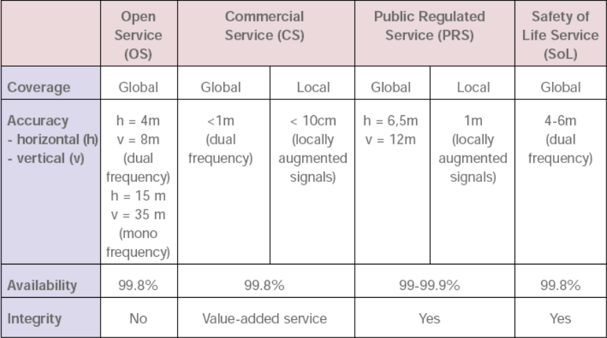
A key asset of GALILEO will be its above-mentioned ability to offer the integrity required for the provision of service guarantees and for the support of safety-of-life applications. It is planned to provide integrity by broadcasting integrity alerts to the users. These alerts will indicate when the GALILEO signals are outside specification. The user receiver can then reject signals from satellites to which an alert refers or, using the outputs of the receiver signal processing in conjunction with other receiver techniques, such as RAIM (Receiver Autonomous Integrity Monitoring), reduce the influence that these signals have on the final computed position.Three differents types of service will be offered. In the following table it is showed the features of each one of them and their different kynds of transport application.
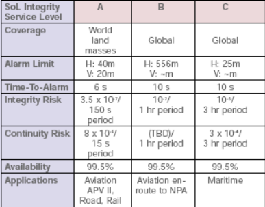
This infraestructure has been designed to obtain a high level of features so can be used even for approaching of CAT-1 without any kind of GBAS (Ground Augmentation System). Galileo will offer differents sort of services with the characteristics showed below, in the following table:
The “Safety of life” requirement, applicable with good visibility of the sky as seen by ships at sea or aircraft in flight, is aimed primarily at safety-of-life applications.4 metres is the vertical accuracy requirement for civil aviation CAT-I precision approach and landing.
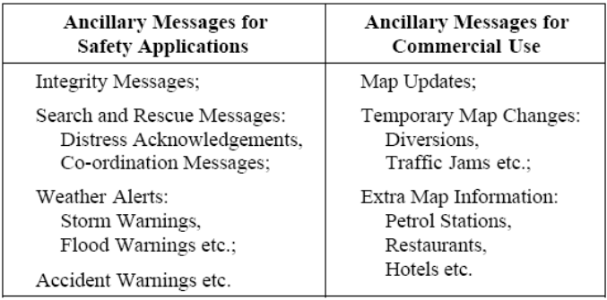
A wide range of data message rates, from 250 bit/s to 1500 bit/s, is being considered.Low data rates cause minimum disturbance to the navigation signal. High data rates maximise the potential for adding ancillary messages and this feature is fundamental for the implementation of GALILEO in the area of the air navigation. For which a wide range of applications can be imagined, as shown the next table:
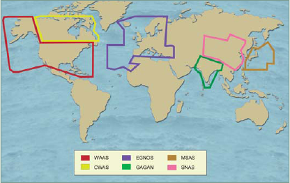
Satellite-Based Augmentation Systems (SBAS) are networks of ground relay stations and geostatic satellites designed to receive satellite navigation signals and transmit corrected time and distance measurements that greatly improve accuracy. Observation and relay stations have been set at known positions all over the world, while their geostatic satellites continuously maintain a fixed position above the Earth. Using these known values for distance, SBAS corrects satellite navigation signals for atmospheric delays, incorrect satellite positioning and poor geometry, sometimes caused by inline or close alignment of satellites, increasing accuracy in specific regions. SBAS is vital to providing the reliability and precision required by aviation. Using the same signal frequencies as satellite navigation, SBAS-enabled receivers are inter-compatible. Three augmentation systems are currently in varying stages of operation and development covering North America, Europe and Asia. These systems are called WAAS, EGNOS and MSAS and are managed by the government of U.S.A., European Union and Japan. More recently the goverments of Canada, Republic of China and India have announced the creation of their own sbas systems; CWAS, SNAS and GAGAN respectively. In the following picture is showed the areas under their range.
Wide Area Augmentation System (WAAS) consists of approximately 25 ground reference stations positioned across the United States that monitor GPS satellite data. Two master stations, located on either coast, collect data from the reference stations and create a GPS correction message. This correction accounts for GPS satellite orbit and clock drift plus signal delays caused by the atmosphere and ionosphere. The corrected differential message is then broadcast through one of two geostationary satellites, or satellites with a fixed position over the equator. The information is compatible with the basic GPS signal structure, which means any WAAS-enabled GPS receiver can read the signal.
Specified performance for WAAS

The European Geostationary Navigation Overlay Service (EGNOS) is a joint project of the European Space Agency (ESA), the European Commission (EC) and Eurocontrol, the European Organisation for the Safety of Air Navigation; such association is called European Tripartite Group (ETG). Consisting of three geostationary satellites and a network of ground stations, EGNOS will achieve its aim by transmitting a signal containing information on the reliability and accuracy of the positioning signals sent out by the Global Positioning System (GPS) and the Global Orbiting Navigation Satellite System (GLONASS); and later, when it became operative, the GALILEO system also.
The EGNOS signal will be broadcast by two Inmarsat-3 satellites, one over the eastern part of the Atlantic, the other over the Indian Ocean, and the ESA Artemis satellite which is in Geostationary Earth orbit above Africa. Unlike the GPS and GLONASS satellites, these three will not have signal generators on board. A transponder will transmit signals up-linked to the satellites from the ground, where all the signal processing will take place. The sophisticated ground segment will consist of about 30 ranging and integrity monitoring stations (RIMS), four master control centres and six up-link stations.
The RIMS measure the positions of each EGNOS satellite and compare accurate measurements of the positions of each GPS and GLONASS satellite with measurements obtained from the satellites' signals. The RIMS then send this data to the master control centres, via a purpose built communications network.
The master control centres determine the accuracy of GPS and GLONASS signals received at each station and determine position inaccuracies due to disturbances in the ionosphere. All the deviation data is then incorporated into a signal and sent via the secure communications link to the up-link stations, which are widely spread across Europe. The up-link stations send the signal to the three EGNOS satellites, which then transmit it for reception by GPS and GLONASS users with an EGNOS receiver.

Considerable redundancy is built into EGNOS so that the service can be guaranteed at practically all times. At any one time, only one master control centre will be “the master”, with another on stand-by to take over instantaneously should the first one fail. There is redundancy in the up-link stations, too. Only three are needed to operate EGNOS, one for each satellite. The other three are in reserve in case of failure.
The Galileo test version bed-1 has already been completed and the feature for horizontal accuracy is shown below. In the following graphic is apreciated the role that egnoss will play in the GNSS-1 as well as GNSS-2.

The specified performance for EGNOSS is shown in the following table

MTSAT Satellite-based Augmentation System (MTSAS) is the SBAS developed by the Civil Aviation Bureau, Japan (JCAB). It consists of a geostationary satellite and two centres of control.
The geo-satellite is called Multi-functional Transport Satellite (MTSAT) and has two missions, i.e. meteorological mission and aeronautical mission. The aeronautical mission of MTSAT will contribute to each element of the ICAO CNS/ATM systems, i.e. communication, navigation and surveillance.. Currently there are two satellites in service ,MTSAT-1R and MTSAT-2R, the first was launched in 2003 and the second in 2004.
The MTSAT system will provide direct controller-pilot communication in voice (SAT-Voice) and data (controller-pilot datalink communication: CPDLC), GPS augmentation information, and automatic dependant surveillance (ADS) capabilities. The MTSAT system will not only be capable of handling oceanic ATS communications within the Japanese FIRs, but will also be offered to the civil aviation community in the Asia/Pacific Region as an aviation infrastructure, which could facilitate the implementation of the ICAO CNS/ATM systems.
In order to provide service continuously, even in natural disasters, two aeronautical satellite centers have been implemented at two different locations in Japan, i.e. Kobe (approximately 500 km west of Tokyo) and Hitachi-ota (approximately 100 km northeast of Tokyo).
Groun-based Augmentation Systems are used to enhance the continuity, availability, integrity and precision of GNSS signals within a reduced geographic area. It consists of a ground monitoring station whose locations known with precision. This station evaluates the information received from GNSS satellites, detects clock and other errors and sends a correction signal to airborne receivers through a VHF data links.
There are two kinds, DGPS y RTK which are described below.
A Differential Global Positioning System (DGPS) is a system designed to improve the accuracy of Global Navigation Satellite Systems (GNSS) by measuring infinitesimal changes in variables to provide satellite positioning corrections.
Two or more receivers observe the same set of satellites, taking similar measurements that produce similar errors when positioned closely together. A reference receiver, placed at a known location, calculates its theoretical position and compares it to the measurements provided by the navigation satellite signals. The difference between the two values reveals the measurement error. The reference receiver then transmits a corrected signal to any number of receivers at unknown positions within the area covered by the DGPS. Accuracy of global satellite positioning is thereby increased from 15 meters to within a few meters. This technique compensates for errors in the satellite navigation system itself but may not always correct errors caused by the local environment when satellite navigation signals are reflected off of tall buildings or nearby mountains, creating multi-path signals. The accuracy of DGPS decreases with asynchronous measurement caused by spatial and temporal error decorrelation when the system receivers are set at greater distances apart.

More sophisticated DGPS techniques can increase positioning accuracy to within a few millimeters. Raw measurements recorded by the reference receiver and one or more roving receivers can be processed using specially designed software that calculates the errors. The corrections may then be transmitted in real time or after the fact (post-processing). By applying the corrections and recalculating the position, accuracy from within several meters to within a few millimeters is achieved, depending on the specific methodology used and the quality of the real-time.
Satellite navigation receivers calculate position by measuring pseudo distances from the positioning satellites. These measurements are taken in several different ways. The most common method, used by all receivers, is to calculate the difference between the time a signal is transmitted from a satellite and the time it is recorded by the receiver, using the code embedded in the satellite's signal. This measurement is called code phase, and produces non-ambiguous meter-level results.
There are three types of DGPS using code phase measurement methods. DGPS and LADGPS (Local Area DGPS) typically cover an area up to several tens of kilometers. The coverage area is greatly increased up to several thousand kilometers by a more sophisticated method known as WADGPS (Wide Area DGPS). WADGPS classifies errors into position-dependent and position-independent components creating a secondary set of measurements that are transmitted to the rover receivers. The rover receivers are then able to reconstruct the pseudo range correction most applicable to their actual position and compute an accurate differential position.
A second method serves to compliment code phase measurement by measuring the carrier phase of the satellite carrier wave. This method provides millimeter-level resolution with measurements that are ambiguous to about 19 centimeters.
DGPS using the carrier phase achieves maximum accuracy only when measurement ambiguities are resolved in some way. The static method of ambiguity resolution is related to stationary receivers, with rover receiver point occupation from 30 minutes to several hours or even several days. The rapid static method reduces occupation periods to several minutes, while the kinematic method allows rover receivers to move without constraint.
The principle of DGPS is separated into the following classifications:
| Measurement Type | Real-time or Post-processing | System Type | Accuracy | Coverage Area |
| Code phase | Post-processing | Post-processed DGPS, post-processed LADGPS or post-processed WADGPS | from < 1 m to ~10 m | From several x 10 km to several x 1000 km |
| Code phase | Real time | DGPS, LADGPS or WADGPS | from < 1 m to ~10 m | From several x 10 km to several x 1000 km |
| Carrier phase | Post-processing | Kinematic, rapid static or static | from < 1 cm to several cm | From several km to several x 1000 km |
| Carrier phase | Real time | Real-time kinematic | from < 1 cm to several cm | From several km to several x 10 km |
![]()
The Local Area Augmentation System (LAAS) is an augmentation to GPS that focuses its service on the airport area (approximately a 20-30 mile radius).It is a DGPS with aeronautical purposes.
It broadcasts its correction message via a very high frequency (VHF) radio data link from a ground-based transmitter. LAAS will yield the extremely high accuracy, availability, and integrity necessary for Category I, II, and III precision approaches, and will provide the ability for more flexible, curved approach paths. LAAS demonstrated accuracy is less than 1 meter in both the horizontal and vertical axis.

Real-Time Kinematic (RTK) is a process where GPS signal corrections are transmitted in real time from a reference receiver at a known location to one or more remote rover receivers. The use of an RTK capable GPS system can compensate for atmospheric delay, orbital errors and other variables in GPS geometry, increasing positioning accuracy up to within a centimeter. Used by engineers, topographers, surveyors and other professionals, RTK is a technique employed in applications where precision is paramount. RTK is used, not only as a precision positioning instrument, but also as a core for navigation systems or automatic machine guidance, in applications such as civil engineering and dredging. It provides advantages over other traditional positioning and tracking methods, increasing productivity and accuracy.
Using the code phase of GPS signals, as well as the carrier phase, which delivers the most accurate GPS information, RTK provides differential corrections to produce the most precise GPS positioning.
The RTK process begins with a preliminary ambiguity resolution. This is a crucial aspect of any kinematic system, particularly in real-time where the velocity of a rover receiver should not degrade either the achievable performance or the system's overall reliability.
This tecnich is widely used by surveyors although the usefulness for aeronautical tasks has to be studied
The Ground-based Regional Augmentation System is a blending of SBAS and GBAS concepts to enhance GNSS performance. This concept is SBAS-like in using a distributed network of reference stations for monitoring GPS (or other constellations), and a central processing facility for computing integrity and differential correction information. Instead of transmitting this information to users via dedicated geostationary satellites, GRAS delivers SBAS message data to a network of terrestrial stations for a local check and reformatting. Each site broadcasts a GBAS-like, VHF data signal which can be received by the aircraft to obtain augmentation data for both en route as well as terminal area approach and departure operations.
In future, voice communication will be used for critical messages, such as vectoring to avoid traffic and landing clearance at airports with heavy traffic. It will serve as back up for data link. VHF analogue radios available today are not compatible with upcoming new technology. The VHF Data Link (VDL) operation requires a VHF digital radio (VDR). VDL is essential for ATN implementation and consequently, for greater use of ATS data links. The availability of airborne equipment manufactured in series, including digital radios, will make it possible to equip a larger number of aircraft. The VDL formats specify a protocol for delivering data packets between airborne equipment and ground systems similar to that used in the aircraft communication addressing and reporting system (ACARS). The difference is that the VDL provides a capacity 10 times greater than the equivalent of 25 KHz VHF channel.
Particularly all the GBAS need a reliable way of communication to transmit from the ground staion to the airbornes, VDL looks the best solution but has to be improved to reach the ICAO coummunication standards. Nowadays the VDL mode 2 is in use and the mode 4 in developing phase, it is expected to be implemented after the 2010 year. The VDL mode 3 will not be in service and his study has been left.
The use of VHF analogue radios for data exchange was started by air lines in the late 70s. Current air borne radios have been used to transmit data between operators and their aircrafts by means of special ground-based stations and interconnection networks. The so-called ACARS system has been developed and has grown considerably, with limited use for ATC communication. This mode has been especially designed to use ACARS modulation equipment and radio. ACARS and VDL mode-1 is a low speed bit oriented data transfer system. It uses carrier sense multiple access (CSMA) methodology. The new development has overtaken VDL mode-1 and is no longer in use.
It is improved version of the VDL- Mode 1 and also uses same technology, but is not capable of handling voice communication. Average data transmission is 31.5 kbps. It employs a globally dedicated common signaling channel of 136.975 MHz. Limited commercial service are available at this time, as aircraft operators and service providers are able to introduce new equipment
It is an integrated digital data and communication system that makes it possible to use four radio channels on a carrier (with a 25 KHz spacing). It uses a data link technology called TDMA. The data capability provides a mobile sub network i.e. compliant to aeronautic traffic network (ATN). It is presently is not available for operational use.
It also has navigation and surveillance capabilities and uses a data link technology called self-organizing time division multiple access (STDMA). In this mode station, stations transmit their geographical position together with data message in time slots that are dynamically modified at frequent intervals.
Before starting a transmission using the STDMA technique, the aircraft keeps listening watch on the frequency to be used and establish a track and a table of time slots of all other aircrafts. An algorithm in the aircraft transceiver selects a free slot or takes the slot of the most distant aircraft. This modulation system allows distant stations to transmit in the same slot with a minimum of interference. STDMA does not have voice communication capability. In this mode aircraft is not involved in any manual frequency tuning for any station change. Even so, reception of the geographic position of other aircraft gives a surveillance capability, which is candidate technology for ADS-B operations.

Aircraft-based augmentation is achieved by features of the onboard equipment designed to overcome performance limitations of the GNSS constellations. ABAS equipment to date has been designed to resolve integrity deficiencies, although future systems may address other aspects. The two systems currently in use are Receiver Autonomous Integrity Monitoring (RAIM) and the Aircraft Autonomous Integrity Monitor (AAIM).
RAIM provides integrity by detecting the failure of a GNSS satellite. It is a software function incorporated into GPS receivers designed to meet TSO-C129, C145, C146 or later versions of these standards. GPS systems with RAIM normally provide three modes of operation:
RAIM may be either Fault Detection (FD) or Fault Detection & Exclusion (FDE), although the majority of existing receiver designs do not include FDE.

FD compares position and time information derived from combinations of four satellites in a set of at least five satellites. In this way, a faulty satellite can be detected and the pilot provided with a warning that the system should no longer be used for navigation. RAIM messages vary between receivers, but there are generally two types. One type indicates that there are not sufficient satellites available to provide RAIM integrity monitoring and another type indicates that the RAIM integrity monitor has detected a potential error that exceeds the limit for the current phase of flight (en-route, terminal or approach). Without RAIM capability, the pilot has no assurance of the accuracy of the GNSS-derived position.
A RAIM hole occurs for the period of time that there are insufficient GNSS satellites in view to provide an integrity check at a given location. In some parts of Australia, particularly southern Australia, there are fewer than five GPS satellites in view for short periods. With only four satellites in view, RAIM may be achieved with barometric altitude aiding to provide the fifth data input. RAIM holes are predictable and GPS NOTAMS (for FD functions with barometric aiding) are issued for flight planning purposes by Airservices Australia.
FDE needs six inputs and, like FD, may use barometric aiding as a data source. With six or more visible satellites FDE will not only detect a faulty satellite but also remove it from the navigational solution and continue to provide FDE or FD with the remaining satellites. FDE is required for oceanic approvals using GPS equipment and mandated in the TSO-C145 and C146 standards.
The AAIM uses the redundancy of position estimates from multiple sensors, including GNSS, to provide integrity performance that is at least equivalent to RAIM. The multi-sensor airborne augmentation systems may be certified in accordance with TSO-C115 as amended. A common example of AAIM uses inertial navigation solutions as an integrity check of the GPS solution when RAIM is unavailable but GPS positioning information continues to be valid.
INMARSAT (International Maritime Satellite Organization) is an international organization established in 1979 and operates as a cooperative society. At the beginning it was settled to improve sea communications in order to increase the safety. Nowadays, in addition to offer services of phone network and data transmission to ships and sea-platforms, it also provides them to the aeronautical comunity and mobile phone network. In its origins, 26 countries founded the organization but now it is formed by 79 members, from which U.S.A is the owner of the biggest part (23%), and United Kingdom and Norway have 11% and 10.5% each one.
Currently are working two generations of satellites (I-2, I-3), and one more (I-4) will be launched this year (2005). Each new generation improves the features of the Inmarsat system to obtain a better broadband and increase the different types of services.
Inmarsat's primary satellite constellation consists of four Inmarsat I-3 satellites in geostationary orbit. These are currently backed up by a fifth spacecraft that can be brought in to provide additional capacity. Between them, the main "global" beams of the satellites provide overlapping coverage of the whole surface of the Earth apart from the poles. A geostationary satellite follows a circular orbit in the plane of the Equator at a height of 35,600km, so that it appears to hover over a chosen point on the Earth's surface. These satellites are supported by four previous-generation Inmarsat-2s, also in geostationary orbit. Each satellite covers one third of the surface of the world proximately, but thay are situated over one strategic region forming 4 regions as the following graphic shows:

The satellites are controlled from the Satellite Control Centre (SCC) at Inmarsat HQ in London. The control teams there are responsible for keeping the satellites in position above the Equator, and for ensuring that the onboard systems are fully functional at all times.
Data on the status of the nine Inmarsat satellites is supplied to the SCC by four tracking, telemetry and control (TT&C) stations located at Fucino, Italy; Beijing in China; Lake Cowichan, western Canada; and Pennant Point, eastern Canada. There is also a back-up station at Eik in Norway.
The job of the satellites will be to support the new Broadband Global Area Network (BGAN), currently scheduled to enter service in 2005 to deliver Internet and intranet content and solutions, video-on-demand, videoconferencing, fax, e-mail, phone and LAN access at speeds up to 432kbit/s almost anywhere in the world.
INMARSAT offers differents kind of services for different purposes. The aeronautical ones are:
Therefore the contribution to the development of the strategy CNS/ATM due to INMARSAT is summarized in three points:
Controller-pilot datalink ;Starting with the Pacific and the North Atlantic, ATC providers have introduced two Inmarsat-supported techniques - automatic dependent surveillance (ADS) and controller-pilot datalink communications (CPDLC) - that are beginning to deliver significant improvements, with further benefits in prospect.
Satellite navigation; The accuracy, availability and integrity of the data supplied to receivers aboard aircraft by GPS and Glonass are augmented by signals broadcast by the Inmarsat I-3 satellites, and Galileo is expected to benefit in the same way.
Voice via Inmarsat;The flight-deck voice capability offered by Inmarsat is used regularly for non-routine communications with the ground, allowing the crew to speak directly to flight dispatch, maintenance and other airline departments. But it also has a number of features allowing it to be used dependably for communications in an onboard emergency. There is at least one significant uncertainty about the future shape of the global air traffic system. While ICAO has mandated the development and implementation of the Aeronautical Telecommunications Network (ATN) to support the efficient, standardized flow of data within the system, the interim use of FANS 1/A avionics and the established Acars datalink format for ADS and CPDLC is increasingly common among international airlines. The Inmarsat Aero system can accommodate both data formats.
They are two example of private companies in the sector of communications, although don´t offer specific services to aircraft communications, they could play an important role in ATM, but is necessary to plan this possibility with an economical point of view and to certify the services they provide.
EUTELSAT has been active fromn 1977 years in commercial satellites communications and owns one of the youngest fleets in the world. Their orbital positions are from 15 degrees West to 70.5 degrees East providing coverage in this way to the 90% of worldwide population across Europe, Asia and America. Satellite control and operations of the company's fully-owned satellites is managed through its teleport in Rambouillet (France) which is also fully equipped to service postlaunch satellite manoeuvres.
His fleet is composed of 23 satellites which serve landbased, maritime and in-flight communications requirements. They are used for video broadcasting to cable and satellite homes, satellite newsgathering and programme exchanges. Their orbital position are shown in the picture below.

Founded in 1964, INTELSAT was the first organization to provide global satellite coverage and connectivity. Today INTELSAT owns and operates a global communication satellite system providing capacity for voice, video, corporate/private networks and Internet in more than 200 countries and territories, that means 99% of the woldwide population, with a fleet of 27 satellites. Their position are shown in the following graphic.

All transmissions via Eutelsat satellites are subject to certain standards and parameters in order to guarantee high quality reception and the safety of the overall system, for that reason either system precise of big ground net spread around the world to monitore and transmit information to the satellites.
These systems are widely used by different kind of companies, not only for communication ones as television channels, newspapers or mobile phone operators. They offer the possibility to set a network for a company with almost wolrdwide goverage, reliability (availability of 99.995% in INTELSAT transponders) and not a huge cost, allowing a fast exchaging of data and information.
Data transmission in one-way or two-way, fax, telephony, internet connection are the typical services offered, but nowadays the VSAT technology is taking more importance as well as all kind of communications available for ship fleets, even they broadcast the GPS signal in some areas. It doesn´t exist applications for aircraft currently, but the use for air transport is evident and the possibility to allowe passengers different services as internet connection, fax,... could be possible. Although to play a role in the future CNS/ATM concept is necessary to define the standars which these systems have to reach and dicuss the exact task which they would do.
The Iridium system is being funded by Iridium Inc., a diverse international consortium of telecommunications and industrial companies. Motorola is the prime contractor to Iridium Inc. for the procurement of the Iridium system. , it began service to the U.S. Government in December, 2000. On March 28, 2001, commercial satellite communications services were launched to heavy industry and other government customers. The marketing strategy will be to focus on industrial clients whose operations require reliable communications to and from remote areas of the globe where terrestrial systems are not available. The Iridium system has the unique ability to reach all of the world's remote areas, including the airspace, the oceans and the many under-developed parts of the globe that currently have no communications systems. Specifically, the company will pursue industrial segments including aviation, maritime, oil & gas, mining, heavy construction, forestry, emergency services, and the leisure market.
The Iridium constellation consists of 66 satellites in near-polar circular orbits inclined at 86.4° at an altitude of 780 km. The satellites are distributed into six planes separated by 31.6° around the equator with eleven satellites per plane. There is also one spare satellite in each plane. With a satellite lifetime of from 5 to 8 years, it is expected that the replenishment rate will be about a dozen satellites per year after the second year of operation. The altitude was specified to be within the range 370 km (200 nmi) and 1100 km (600 nmi). The engineers wanted a minimum altitude of 370 km so that the satellite would be above the residual atmosphere, which would have diminished lifetime without extensive stationkeeping, and a maximum altitude of 1100 km so that the satellite would be below the Van Allen radiation environment, which would require shielding.
Each satellite covers a circular area roughly the size of the United States with a diameter of about 4400 km, having an elevation angle of 8.2° at the perimeter and subtending an angle of 39.8° with respect to the center of the earth. The coverage area is divided into 48 cells. The satellite has three main beam phased array antennas, each of which serves 16 cells.
The period of revolution is approximately 100 minutes, so that a given satellite is in view about 9 minutes. The user is illuminated by a single cell for about one minute. Complex protocols are required to provide continuity of communication seamlessly as handover is passed from cell to cell and from satellite to satellite. The communications link requires 3.5 million lines of software, while an additional 14 million lines of code are required for navigation and switching. As satellites converge near the poles, redundant beams are shut off. There are approximately 2150 active beams over the globe. The configuration of the IRIDIUM is shown in the following picture.

IRIDIUM can provide 4800-bps data rate for voice communications and support 80 simultaneous users per cell and 172,000 simultaneous users system wide. The end-to-end delay is able to meet the standard minimum of 400 ms.
In his developing phase, Iridium was intended to provide both safety (ATS & AOC) and non-safety (AAC & APC) services across all authorized frequencies. Nowadays it only offers non-safety communications service,ground to air, air to ground and aie to air; besides other services as fax, voice, data transmissiom or internet connection. It was supposed to be the main tool for the aeronautical communications but it didn´t reach the expected features, currently it is the base to develop the "aero fleet" project (based on MASSAO project) by ESA, a system to allow an operating personal centre tracking, monitoring and communicating with an aircraft in all weather conditions and in large distance from the centre via satellite.
The VSAT market has been going since the early 1980s and the launch of the first one-way VSAT system by Equatorial of California. Towards 1985 the first interactive star systems began to be seen and it wasn't until 1989 that the first mesh telephony products were really sold.
VSAT is the acronym of Very Small Aperture Terminal, an earthbound station used in satellite communications of data, voice and video signals, excluding broadcast television. A VSAT allowed one-way or interactive communications.
The data transmission rate on the return link, in the direction from the VSAT to the hub, is typically from a few 100 bit/s to 512 kbit/s. The number of VSAT sites sharing a return link and the number of return links is adjustable to match actual traffic patterns without unacceptable congestion. Where higher return link bit rates are required up to say 2 Mbit/s a continuous return link carrier is used (SCPC) Single channel per carrier.
In the outlink direction from the hub to the VSATs continuous carriers are used, typically more than 256k bit/s and up to 60 Mbit/s. For strongly asymmetrical services, such as Internet or Intranet broadband applications extra outlink capacity up 60 Mbit/s is easily added. Each VSAT is restricted to extract from the data stream only those packets of data intended for it's ports. One outlink may be shared by 5 to 32000 VSAT sites, according to the traffic load.
There are many further possibilities. Point to point VSAT networks (2 terminals only) are possible with 2 Mbit/s each way, carrying a mixture of data and voice traffic
Generally, these systems operate in the Ku-band (10/14 GHz) and C-band (6/4 GHz) frequencies. As a rule of thumb C-band (which suffers less from rain attenuation, but requires larger antennas) is used in Asia, Africa and Latin America whilst Ku-band (which can use smaller antennas, but suffers from rain fade in a monsoon-like downpour) is used in Europe and North America. Typically, interactive Ku-band antenna sizes range from 75 centimetres to 1.8 metres and C-band from 1.8 metres to 2.4 metres. One way systems can use antennas as small as 45 centimetres.
One-way or broadcast systems rely on a transmitting station which transmits one or more carriers to the satellite which re-broadcasts the signal over its coverage area. All receive-only VSATs under the satellite footprint can then receive the signal or the user/operator is able to define groups of VSATs from one to all on the network.
Interactive VSAT systems come in two main network topologies - star and mesh. The former tends to be based either on a shared access scheme (TDM/TDMA), which is designed to support transactional processing applications, or on a dedicated link (the satellite equivalent to a leased line). The latter usually uses links which are set-up and torn-down on request to establish a direct link between two sites on a demand assigned basis. Either technics of communication are described below:
This is how a star data, TDM/TDMA VSAT network works using a hub station. All the channels are shared and the remote terminals are online, offering fast response times. Consequently, TDM/TDMA systems are comparable with terrestrial X.25 or frame relay connections.

However, mesh networks which use capacity on a demand assigned multiple access (DAMA) basis take a different approach. The master control station merely acts as a controller and facilitator rather than a hub through which traffic passes as in a star network. However, these connections take a little time to set-up and thus, mesh/DAMA systems are often equated to a terrestrial dial-up connection.

There are also mesh systems which use a TDMA access scheme where all of the terminals in a network receive and transmit to the same channel, selecting different time slots because each terminal is aware of what the others have reserved. In the past this type of system has been costly and therefore, reserved for large scale trunking applications, but, more recently, costs have come down considerably and now they can be cost competitive with SCPC/DAMA systems for thin route applications as well.
Point-to-point SCPC (single channel per carrier) links are the satellite equivalent of a terrestrial leased line connection. They are usually set-up on a permanent, 24 hour basis and are thus more costly in satellite capacity and less efficient if not used all the time. However, they do support high bandwidths (typically from 9.6 kbps to 2 Mbps) and can easily be used to carry data, voice and even video traffic.

All other systems are usually a variation on one of the themes described above, either in a star, mesh or hybrid (star and mesh) configuration. Most of the TDM/TDMA manufacturers also offer a mesh product which can be deployed in a hybrid-ised configuration, sharing common components such as antennas and RF units, at a remote site.
The Satellite Data Link System (SDLS), is a satellite-based radio communication system, which under feasibility studies operating since 1994.Supported by ESA Telecom, a consortium of European companies led by Alcatel of France are embarking on a satellite project worth 4.5 million Euro that will help ease congestion of the VHF spectrum to meet the ever increasing communication requirements resulting from the air traffic growth, which are predicted to saturate current systems around 2010 to 2015.
SDLS will take over for ground-based VHF systems to provide digital data transmissions between aircraft and ground facilities, including control towers and airline operations control centers. It aims to provide:
It could also be integrated in the Galileo satnav system to supply navigation and communications services to civil aviation authorities
The SDLS Concept can take advantage of both the existing AMSS deployed ground infrastructure using large Ground Earths Stations (GES) and small VSAT-based Ground Earth Stations, which can be deployed more easily and cheaply. The key technical characteristics of the SDLS concept are:

SDLS is designed to demonstrate technical performances to a standard necessary to meet communication requirements of future ATM systems and, more specifically, Air Traffic Services (ATS) applications, as currently specified by the International Civil Aviation Organisation (ICAO).
Nowadays the system is still in its developing phase with two prototypes located in Toulouse and Rome, thay are called SDSL Demonstrators and are composed by two Aeronautical Earth Station (AES - low cost approach) and two Ground Earth Stations (GES). The SDLS Demonstrator proves that the performances achievable using a satellite media are compatible with the requirements of the aeronautical community for ATM missions. Performance has been evaluated at the application service level. Initial evaluation has shown that SDLS can meet many of the communication requirements of emerging ATS data applications being defined by Eurocontrol.
Due to the succes of the experiments the system development road map aims at an operational introduction date of around 2010 and the results of this work are now being used to help define the next generation satellite system.
Management and Supervision System for Special Aircraft Operations (MASSAO) is a project developed by ESA in collaboration with Euro Telematik AG and it is related to operation management of special aircraft fleets, all-weather operation of aircraft, and tracking of air vehicles independent from ATC radar coverage. This system allow an operating centre personnel to track, monitor, and communicate with aircraft within their full operating range, even in large distances from the centre, via satellite communication.
The AeroFleet system is a solution,based on MASSAO concept, for operators of small and medium size aircraft and helicopter fleets providing digital air-ground communication for efficient fleet management. The system is capable to provide local and global communications, digital 2-way ground-air messaging, position reporting and navigation, airborne mission management, uplink of weather information.
The system consists of the following components:
The system works in the following way; the CDTI-2000 unit serves as the core unit and the crew interface to the on-board system. It exchanges information with the satellite communication transceiver via a serial interface. After the transmission from the transceiver to the satellite communication service providers ground segment the message is forwarded by e-mail to the AeroFleet Server. The ground station AeroFleet retrieves the e-mail and decodes the message.
A number of dispatcher work stations (Clients) can be connected to this server in the operators centre. Staff can monitor and manage aircraft operations.
Messages from the ground system to the CDTI-2000 are handled in a similar way. In this case messages can be send from the server to the on-board transceiver by means of a dedicated e-mail address. The data is then transmitted further to the CDTI-2000.

This system provides a low cost to manage small fleet with a small infrastructure. It shall be the solution fo small companies to achieve good low cost operations. Flexibility, big coverage, low cost, compatibility with VHF communications are the strong points making it useful for many aplications (medical asistance, rescue, fire extinctions,...). It gives a cue of the development of the future ATM concept, with an important role for the satellites, wide coverage, low cost and easy implementation.

Multi Function Display CDTI-2000
Optimised Procedures and Techniques for the Improvement of Approach and Landing (OPTIMAL) is large scale European project involving 24 partners and which is aiming to define and validate innovative procedures for approach and landing phases of both aircraft and rotorcraft in a pre-operational airport environment. It started early 2004 and will last for about 4 years. The objective is to increase airport capacity while minimising noise nuisance and improving operational safety. Those achievements will be enabled by today available precision approach landing aids (ILS, MLS), as well as new satellite-based guidance systems ( SBAS, GBAS), etc, more accurate navigation means (RNP 0.1), enhanced airborne systems, such as autonomous FLS, for Non-Precision Approaches and enhanced ground systems to support Air Traffic Control. The target time frame for the operational implementation of the OPTIMAL proposed operational concept is 2010 and beyond.
The objectives of the OPTIMAL project are:
Expected Benefits:
"For all phases of flight, to enable the safe, economic, expeditious and orderly flow of traffic through the provision of ATM services which are adaptable and scaleable to the requirements of all users and areas of European airspace. The services shall meet demand in a cost-effective way, be globally inter-operable, operate to uniform principles, be environmentally sustainable and satisfy national security requirements."(ATM strategy for the years 2000+ vol.1 , Eurocontrol, ed. 2003).
The necessity of a change in the current ATM system is evident but also in the goals that are set. The new worlwide situation, the privatization of the aerospacial industry, the recent terrorist attacks and the continous globalization make the international community change the point of view to plan the new ATM structure, some concepts has to be under consideration besides the capacity, safety and accuracy.
To enhance the security to confront intentional attacks, to develop new technologies with an affordable rate of cost-effectiveness, to provide a global seamless coverage, the interoperability between the differents systems and a strong cooperation with the military system; all of them are the foundations for the future Air Traffic Management.
The satellite techonologies and systems will play and important role in the next years because combine all the features required for the ATM strategy. Some of them, as GNSS phase 1, are in an advanced state of development and its implementation is nowadays almost completed. Other ones are still in developing phase but to reach all the goals more systems have to be created.
The ARTES programme of the European Space Agency (ESA) describes all the projects achieved by this organization and it is a good indicator about technological evolution in the following years.
All the aforementioned systems complywith the purposes in each element of ATM, communication, navigation and surveillance (CNS). These goals are described in the following graphic.

Communication; the main system to provide this service is the constellation of INMARSAT which was created with such purpose. Other private companies as INTELSAT or EUTELSAT could be a good option for exchanging information but they don´t comply with the ICAO requirements for aeronautical communications; however, the combination with IRIDIUM could provide a good back-up system for communications with a wide coverage. In anyway, with such systems, the passengers will obtain access to fax, telephony and internet services during the flight although, by the moment, they cannot be used for safety communications.
In the other hand the GNSS infrastructure has the capability to be used for communications giving, enhacing the coverage.
For these reasons it is foreseen that satellite system will replace the HF communications in ocean regions soon, but VHF Data Link systems will be a necessary complement for such scope. The mode 2 is in use currently and the mode 4 looks to be the next generation with the capability of hold voice communications.
Satellite Data Link System (SDLS) is an ambicious project managed by ESA which will share tasks with VDL, discharging the saturated VHF band.
The aero fleet project is a good example of a satellite solution for private companies although it has not any usefulness for safety purposes.
Navigation; GNSS will provide a seamless worldwide coverage with enough precission to en-route phases of flight, nevertheless for high density areas and approaching phases it is completely necessary augmentations or ground systems. The second phase with only the two constellations (GPS, GALILEO) and SBAS reach the required performance till CAT I, this is far away from a global coverage but the combination with other kind of augmentations (RAIM, AAIM, LAAS) or ground systems (MLS, ILS, VOR-DME).
INMARSAT and the VDL technology support also the navigation system being a part of SBAS and GBAS respectively.
Private companies of communications might send also the GPS signal in order to enhance it, although they don´t comply with ICAO standards.
Surveillance;Primary Surveillance Radar (PSR), Monopulse Secondary Surveillance Radar (MSSR) and Mode S are the systems in use currently but they cannot be consistent with the gate-to-gate concept because in remote areas the service is not provide. The solution aims to be the Automatic Dependent Surveillance, Contract (ADS-C) or Broadcast (ADS-B).
The general application of ADS will require that all aircraft in a region of airspace be equipped with satellite navigation and some form of data link. Thus GNSS, communication satellites and VDL techniques (in special mode 4) are critical for the development of such technology.
Below is shown a table with a foreseen about the evolution the technology for the different elements of the ATM in every kind of airspace, nowadays an din the year 2015.
| Airspace | Function | Current system | Future System |
| Oceanic continental En-route airspace with high / low-density traffic | Navigation | OMEGA/LORAN-C NDB VOR/DME Barometric altimetry INS/IRS | RNAV/RNPGNSSBarometric altimetryGNSS altitudeINS/IRS |
| Continental airspace with high-density traffic | Navigation | VOR/DME | Barometric altimetry GNSS altitude |
| Terminal areas with high-density | Navigation | NDB VOR/DME ILS Barometric altimetry INS/IRS | RNAV/RNP |
"The `gate-to-gate' scope is considered to start at the moment the user first interacts with ATM and ends with the switch-off of the engines, including also the processes of charging users for ATM services. The scope does not encompass ATM processes only."(ATM strategy for the years 2000+, Eurocontrol, ed. 2003)
This short definition given by the EUROCONTROL ´s document doesn´t clarify the real scope of the concept.
Gate to gate is one fo the main goals for the future ATM. The-state-of-art and his evolution aim to such concept, developing the technology which will make it possible.
The implementation is predicted to be between the years 2015 and 2020 and the question whether finally it will be made or not will try to be answered in this chapter.
The neccessity of a change in the air traffic system is evident and anowadays big efforts are made by the international community to fin out a solution. Nowadays a lot of resources are invested in that concept in particular and in the improvement of ATM services in general.
Three points should be discussed to assess the feasibility of Gate to gate concept and they are:
The satellite systems described all project long can support the neccessities of the gate to gate concept. GNSS will provide an almost seamless navigation system till CAT-1 in all phases of flight, but with the use of the augmentation systems based on ground and on airborne could replace the ILS and MLS. However the installation of Surface Movement Guidance and Control System are needed to a complete gate to gate (GtG) service. Coummunications, data link or voice, are other fundamental part which can be provided by satellite systems, INMARSAT mainly with IRIDIUM, GNSS and VDL technics as well they play and important role in ADS.
A reliable network of information has to be achieved for a correct management the flights. In that scope, VSAT technology, even provided by private companies, could be the solution in such areas with a low ground telecommunication infrastructure.
The current state of the art and programmes like ARTES which describes the technology in researching an developing in the next years, aims to the technology for GtG operations will be ready in 2015.
Nowadays some scenaries have been prepared to test the feasibility of the appliccation of that concept. An instance about the different parts of a flight under GtG and all elements involved are showed in the following table.

a X means it takes part directly and a ? just supports in that phase.
In summarize, two are the points to improve, a reliable flight management system which could solve make changes in time and an efficient route planning therefore the application of free flight concept is also neccessary. The technology to support such concepts already exists but his implementation presents the biggest problem due to the big differences between the countries. However its applicatio in the european space shouldn´t present a unaffordable problem because his proximity in technology, legislation and cooperation.

From 2020 on a totally new system of ATM will be working, the management of the if the disponible airspace will be more efficient, safety and with more capacity without forget the rate cost-effectiveness which is indispensable for the correct implementation and acceptance in the private sector. However new problems will appear, some of them due to the new requirement in air traffic market and others because the inherent errors of the new systems and its prediction suppose a big problem.
In the future, the demand for air traffic services will not only increase but also will likely shift from scheduled operations towards more unscheduled operations for air taxi, charter, fractional ownership, and on-demand small low-cost aircraft. As the metropolitan areas continue to grow, the satellite airports around major hubs will provide a wide range of flight options for people to fly between their homes and places of business or pleasure.
Furthermore the satellite systems are liable to suffer attacks to their signals because they are weak and there is not redundant system. In addition the primary radar surveillance (PSR) cannot disapeared totally because is the only one pasive surveillance system and in high latitudes not all the satellites can provide service. For those reasons the feasibility of GNSS and other satellite systems is debatable.
The navigation will be widely covered by GNSS. This is a cheap system with a seamless coverage and with the correct augmentations can reach the navigation performances defined by ICAO. It looks to be the perfect solution for a free flight system. However, how was aforementioned, the weakness of their signal and his lack of redundance make difficult his implementation as sole system.
In oceanic areas aims to be the real sole system because the impossibility to place other systems but in continetal areas, specially in high density ones, other chances are possible.
DME-VOR and DME-DME can also provide a free flight service, although the navigation features of the first one are very poor the DME-DME system provides a good performance and aims to be the redundant system for GNSS. And may be ILS, or with a higher possibility MLS, the redundant system for approaching operations. The rest of ground systems, for instance NDB, LORAN and might be VOR, will be dismantled between the years 2015 and 2020, as in the ICAO previsions is said.
The saturation of the VHF band and the searching of a global system will make satellite systems play an important role in communications, data link or voice. Although the advantages of VHF over satellites communication and its importance for GBAS will avoid the implementation as the sole system, VDL mode 4 will be essential in this part of the ATM element.
Private companies will be able to offer services to passengers or even aeronautical services to aircompanies. Nowadays communications are fundamental in bussiness this tendency is increasing, services during flight as internet access or data and voice transmission will open a new market for communications. In addition the neccesity of a reliable global net of information for a 4D gate to gate system and the possibility for other systems as IRIDIUM, EUTELSAT or INTELSAT to make navigation functions will promote the participation of the private sector in ATM functions, specially in coummnication ones.
To provide surveillance ADS will be the main system. It will be neccesary a new distribution of tasks between pilot and air traffic controller bur this technic will enhance the safety and reduce the horizontal and vertical separation between aircrafts. Besides VDl and data link satellite will start to play a role in this element of the ATM. However PSR will be always neccesary and radar mode S will complement ADS in high density areas.
Concepts as free flight and gate to gate will be fully implemented so a reliable management of flight will be feasible. Using the new system of navigation and surveillance each company will be able to choose the best path according to the performances of their aircraft. The new system of communication will allow the creation of a net so instant changes in flight plans and a gate to gate management will be possible.
AMSS will play an important role in the future ATM concept. These systems present a lot of advantages over the current ones and in the following years it is predicted the incorporation of private companies in the mobile subnetwork. Possible applications are presented below:
The changes in the following years will transform completely the current system of air traffic management. The neccesity of a change because the big increase of the worlwide air traffic and the limitations of the present exploitation of the airspace have forced to the international community to make a revolution in order to enhance the capacity of the ATM system.
The system of navigation aims to be seamless and with global coverage supporting by the GPS, GLONASS and GALILEO constellations. Such systems with the adecuated augmentations can provide the required service in every phase of flight and implementing the free flight concept. Nowadays the system is not very flexible and the safety separation between aircrafts big. The routes are planned following point to point paths, normally indicated by VOR\DME system. There are big areas where is not possiblle to set any kind of conventional air navigation aid. In instrumental approaching ILS is the most extended, it presents some limitations which will be solved by satellite systems. ILS only allowed the approaching following one path, it means big problems of noise contamination and the impossibility of choose the best route depending on the charateristics of each flight.
Communications are stablished through VHF and HF band. Nowadays the VHF band is almost saturated and only allowed communication in line of sight. HF offers voice communications with a very low quality but a big coverage and are only used in oceanic and high latitudes areas. VDL mode 2 is the solution in short range for the present problems but it is not enough. The incorporation satellite systems in combination with VDL mode 4 will offer a global coverage even in polar circles and oceanic areas with a high reliability.
PSR, SSR and more recently Radar mode S are the only systems in use. As in the aforementioned system its coverage is limited to continental areas and the charge of work to air traffic controller is reaching its limit. The solution is given by the ADS system based on a continuous communication between ATC to aircraft, aircraft to ATC and aircraft to aircraft. They deliver all the information about each airplane to create in every cockpit and ATC a represention of the surrounding air traffic. However that is an active technic and the presence of PSR and at least Radar mode S will be always neccesary.
The conclussion is that the satellite system are the solution to solve the lacks of the present system but it cannot be the sole system as it was predicted because the neccesity of a redundant system, therefore at least DME, MLS and PSR will coexist with satellite systems.
However the implementation of gate to gate,rnav, 4D free flight it is unthinkable without these systems due to their worlwide coverage, high performance and as a very important reason nowadays their rate cost-effectiveness.
In addition the private companies will be able to offer aeronautical services.
| AAC | Airline Administrative Communication |
| ABAS | Aircraft-based Augmentation System |
| AES | Aeronautical Earth Station |
| AAIM | Aircraft Autonomous Integrity Monitor |
| ACARS | Aircraft Communications, Adressing and Reporting System |
| ADS | Automatica Dependant Surveillance |
| ADS-B | Automatica Data Surveillance- Broadcast |
| ADS-C | Automatica Data Surveillance-Contract |
| AES | Aeronautical Earth Station |
| AMSS | Aeronautical Mobile satellite System |
| ATC | Air Traffic Controller |
| ATM | Air Traffic Management |
| ATN | Air Telecommunications Network |
| ATS | Air Traffic Service |
| B-RNAV | Basic- Random Navigation |
| CDMA | Code Division Multiple Access |
| CDTI | Cockpit Display of Traffic Information |
| CNS | Communication, Navigation and Surveillance |
| CPDLC | Controller-Pilot Datalink Communication |
| CSMA | Carrier Sense Multiple Access |
| CTS | Command Tracking System |
| DAMA | Demand Assigned Multiple Access |
| DGPS | Differential Global Position System |
| DME | Distance Measurment Equipment |
| DOD | Departament of Defense |
| ECAC | European Civil Aviation Conference |
| EGNOS | European Geostationary Navigation Overlay System |
| ETG | European Tripartite Group |
| EUROCONTROL | European Organisation for Civil Aviation Equipment |
| FANS | Future Air Navigation System |
| FUA | Flexible Use of Airspace |
| GBAS | Ground-based Augmentation System |
| GCS | Ground-based Control Complex |
| GEO | Geostationary Orbit |
| GES | Ground Earth Station |
| GLONASS | Global Orbiting Navigation Systems |
| GNSS | Global Navigation Satellite System |
| GPS | Global Position System |
| GRAS | Ground-based Regional Augmentation System |
| GSS | Galileo Sensor Stations |
| GtG | Gate to Gate |
| HP | high precission |
| ICAO | International Civil Aviation Organisation |
| IFR | Instrument Flight Rules |
| ILS | Instrument Landing System |
| JCAB | Japan Civil Aviation Bureau |
| LAAS | Local Area Augmentation System |
| LADGPS | Local Area DGPS |
| LEO | Low Earth Orbit |
| MASSAO | Management and Supervision System for Special Aircraft Operations |
| MCS | Master Control Station |
| MEO | Medium Earth Orbit |
| MLS | Microwave Landing System |
| MTSAS | MTSAT Satellite-based Augmentation System |
| MTSAT | Multi-functional Transport Satellite |
| NDB | Non-Directional Beacon |
| NM | Nautic Miles |
| NOTAM | Notice to Air Men |
| OPTIMAL | Optimised Procedures and Techniques for the Improvement of Approach and Landing |
| PPS | Precise Positioning Service |
| P-RNAV | Precission Random Navigation |
| PSR | Primary Surveillance Radar |
| RAIM | Receiver Autonomous Integrity Monitoring |
| RAIM-DR | RAIM-Dead Reckoning |
| RAIM-FD | RAIM-Fault Detection |
| RAIM-FDE | RAIM-Fault Detection & Exclusion |
| RIMS | Runway Incursion Monitoring System |
| RNAV | Random navigation |
| RNP | Required Navigation Performance |
| RTCA | Radio Technical Commission for Aeronautics |
| RTK | Real-Time Kinematic |
| SA | selective availability |
| SBAS | Satellite based Augmentation System |
| SCC | system control center |
| SCPC | Single Channel Per Carrier |
| SDLS | Satellite Data Link System |
| SP | standard precission |
| SPS | Standard Positioning Service |
| SSR | Secondary Surveillance Radar |
| STDMA | Self-organizing Time Division Multiple Access |
| TDM | Time Division Multiplexing |
| TDMA | Time Division Multiplexing Access |
| UTC | Coordinated Universal Time |
| VDL | VHF Data Link |
| VDR | VHF Digital Radio |
| VHF | Very High Frequency |
| VOR | VHF Omni Range |
| VSAT | Very Small Aperture Terminal |
| WAAS | Wide Area Augmentation System |
| WADGPS | Wide Area DGPS |
"Telemedicine via Satellite Services"
Ms. Eli Larsen, EL, National Centre of Telemedisine
Ms. Tove Soerensen, TS, National Centre of Telemedisine
Mr. Erik Otto Evenstad, EOE, Telenor Research and
Developement (ESA report)
"An overview of the IRIDIUM low earth orbit (LOW) satellyte system"
Carl E. Fossa, Richard A. Raines, Gregg H. Gunsch, Michael A. Temple
2950 P St, Bldg. 640 Wright-Patterson AFB, OH 45433-7765
Department of Electrical and Computer Engineering, Air Force Institute of Technology
"ISA project (Ipv6 - Satellite - Atm for ATN) satellite prspectives for CNS/ATM"
L. Crouzard,G. Gawinowski,C. Musson
"OPTIMAL State-of-the-art Deliverable D1.1"
OPTIMAL Project Co-ordinator Daniel FERRO
Airbus
"C-ATM High-Level Operational Concept Deployable From 2012 Version 1.31"
Michel Stirnemann, Volker Rothmann, Robert Graham, Ray Dowdall, Ros Eveleigh,
"Guidelines for Navigation using GNSS"
civil aviation safety authority australia
"The modernization of GPS: Plans, New Capabilities and the Future Relantionship to Galileo"
Keith D. McDonald; Navtech Consulting, Alexandria, VA USA
"GNSS sole service feasibility study"
France Développement Conseil (Vincennes, France)
"Integrated Free Flight and 4-D Gate-to-gate Air Traffic Management, Possibilities, Promises and Problems"
F.J. Abbink
National Aerospace Laborator y NLR
"Nominal scenario NO 1 (GATE-TO-GATE) - 2011"
OCD/OATA ConOps Development
"Air Traffic Management strategy beyon the years 2000+ vol 1 y 2"
ed 2003 eurocontrol
"The galileo satellite system and its security implications"
Gutsav lindström, Giovanni Gasparini
"GALILEO : Satellite System Design And Technology Developments"
J. Benedicto, S.E.Dinwiddy, G. Gatti, R. Lucas, M. Lugert
European Space Agency
"Communication Navigation Surveillance / Air Traffic Management (Cns / Atm) Beyond 2012"
Arjun Singh
Airport Authority of India
"European aeronautics: a vision for 2020"
Pedro Argüelles, Manfred Bischoff, Philippe Busquin, B.A.C. Droste, Sir Richard Evans, Walter Kröll, Jean-Luc Lagardère, Alberto Lina, John Lumsden, Denis Ranque, Søren Rasmussen, Paul Reutlinger, Sir Ralph Robins, Helena Terho, Arne Wittlöv
"Overview of Civil Aviation Satellite Communications & Spectrum Requirement Refinement"
Phil Platt - QinetiQ, Philippe Renaud, Geoff Bailey
EATMP
"Performance, Capacity and Limitations of AMSS Communications"
Claudio Ripamonti, Vijay K. Konangi, Robert J. Kerczewski
"Joint board on communication satellite programmes ARTES-1 workplan for 2005"
European Space Agency (ESA)
"The nees for a new ATM operational concept a strategic necessity?"
Steve Zerkowitz, Assistant Director Operations and Infrastructure - Europe, IATA
"Link 200+, controller- pilot data link communications ready for 2007 and beyond"
Alex Wandels, LINK 2000+ Programme Manager
ð Asynchronous Time Division Multiple Access (A T D M A)
Asynchronous TDMA (cf. TDMA).
ð Code Division Multiple Access (C D M A)
CDMA uses "pseudo-random code sequences"; they are used by both the mobile station and
the base station to distinguish between conversations. CDMA uses these code sequences as
a means of distinguishing between individual conversations. All users in the CDMA system
use the same carrier frequency and may transmit simultaneously. CDMA is a driving
technology behind the rapidly advancing personal communications industry. Because of its
greater bandwidth, efficiency, and multiple access capabilities, CDMA is becoming a leading
technology for relieving the spectrum congestion caused by the explosion in popularity of
cellular mobile phones, fixed wireless telephones, and wireless data terminals. Since
becoming an officially recognized digital cellular protocol, CDMA is being rapidly
implemented in the wireless communications networks of many large communications
corporations.
ð Frequency Division Multiple Access (F D M A)
FDMA divides radio channels into a range of radio frequencies and is used in the traditional
analog cellular system. With FDMA, only one subscriber is assigned to a channel at a time.
It is the oldest and still one of the most common method for channel allocation. In this
scheme, the available satellite channel bandwidth is broken into frequency bands for different
earth stations. This means that guard bands are needed to provide separation between the
bands. Also the earth stations must be carefully power controlled to prevent the microwave
power spilling into the bands for the other channels.
ð Time Division Multiplexing (T D M)
Technique in which information from multiple channels can be allocated bandwidth on a
transmission system based on time.
ð Time Division Multiple Access (T D M A)
A shared channel access mechanism based on time division multiplexing. TDMA divides
conventional radio channels into time slots to obtain higher capacity Global System for GSM
(Mobile Communications). No other conversations can access an occupied TDMA channel
until the channel is vacated.
This presentation will introduce the language proficiency requirements that are contained in Annexes 1, 6 and 11 and in the PANS-ATM. However and because most of the new Standards are contained in Annex 1, the majority of the presentation will be devoted to Annex 1.
Annex 1 - Basic principles
The language proficiency Standards contained in Annex 1 are fairly comprehensive and, different Standards and Recommended Practices apply in different ways to each specific licences. However, all of them are based on the same following basic principles:
Annex 1 - Details of the Standard
The licences contained in Annex 1 can be divided in three different groups as far as language proficiency Standards are concerned. The first groups is made of the three levels of aeroplane and helicopter licences (PPL, CPL and ATPL) and the Air Traffic Controller and Aeronautical Station Operators licences which have to meet the following Standards:
The second group covers Flight Engineer, Free Balloon and Glider pilots licences. For this second group, the new requirement is a Recommendation to the effect that the licence holder should be able to speak and understand the language used for radio communication.
The third group is made of the Flight Navigator licence. The case of the Flight Navigator is specific and taking into account that some of the navigators are tasked with the handling of radio communication. As a result, the ICAO Council decided that the basic “speak and understand” Standard would apply to flight navigators when they are required to use radio telephone on board. However, the rating scale will not apply to them in 2008.
Annex 1 - Implementation
Application of Language Proficiency Standards to existing licence holders
Application to domestic flight
The language proficiency Standards are ICAO Standards and as such they only apply to pilots who are engaged in international flights and ATCO/ASO providing services to international flights. Hence, States are encouraged by ICAO to use the ICAO Standards for domestic operations.
In which language(s) a pilot or a controller must be tested
Consequences of non-compliance with the language proficiency Standards
Language proficiency provisions contained in the other Annexes
Annex 6 requires operators to ensure that flight crew speak and understand the language used for radiotelephony communications.
Annex 11 requires air traffic service providers to ensure that air Traffic Controllers speak and understand the language used for radiotelephony communications. Annex 11 also contains a Standard dealing with the language to be used in communication between air traffic control units. That language shall be English except when another language is mutually agreed.
Procedures for Air Navigation Services - Air Traffic Management (PANS-ATM): The provisions contained in PANS are complementary to the Standards and Recommended Practices contained in the Annexes. The requirements state that ATS and other ground personnel will be expected to use plain language to the level specified in the ICAO language proficiency requirements contained in Annex 1. This applies in particular to the personnel providing information services in uncontrolled airspace and at uncontrolled aerodromes.


71
Descargar
| Enviado por: | Nabil |
| Idioma: | inglés |
| País: | España |
Todos los derechos reservados.